Summarize
In precision analytical applications such as mass spectrometry, equipment requires high-voltage power supplies that are precisely specified and designed.
Depending on the application, there are different requirements for spectral power supplies - a solution-based approach is needed.
Deploying multiple power supplies in the same device presents additional challenges.
We share how to solve the most common design problems of high-voltage power supplies in mass spectrometry.
1. Ripple reduction outside the power supply
In mass spectrometry applications, high voltage power supplies are required to provide high voltage with minimal
ripple and noise. In high-voltage DC-DC converters, the ripple frequency is related to the switching frequency of the power supply. We specify the frequency of the device in the product data sheet.
Wisman offers a wide range of high-voltage power supplies with low ripple and noise. To further reduce the
output ripple associated with the switching frequency, customers can use additional filtering components.
It consists of resistors and capacitors connected in parallel mode. The RC low-pass filter sets the cutoff frequency,
allowing lower frequency signals to pass through while lowering higher frequency signals.
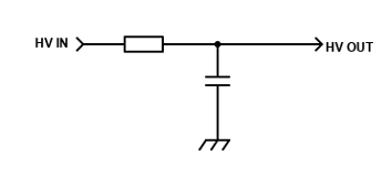
2. Design RC low-pass filter
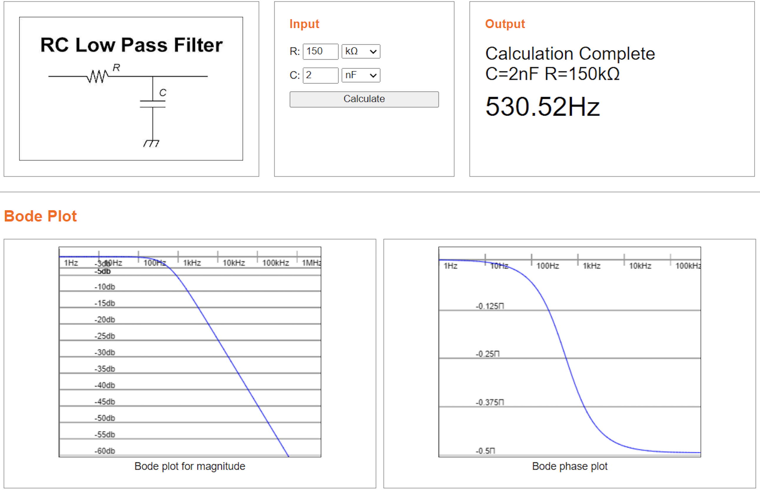
First, we determine which frequencies must be filtered out. In the example below, we have selected 120kHz in this
circuit setup, which is the switching frequency of Wisman's high-voltage module C80N.
The cut-off frequency should be sufficiently different from the frequency to be filtered to allow sufficient damping
of the oscillations.
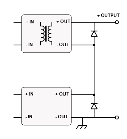
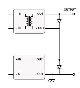
3. Set the cascaded high-voltage power supply
The high-voltage power source in the mass spectrum may operate at a different potential than the earth. This
means that one power source is "suspended" on the reference potential of another power source.
A detector suspended on a lower potential is an example of such an arrangement. The best solution is to use
isolated high-voltage power supplies, where the isolation rating of the high-potential power supply must be at least
equal to the floating voltage.
In the case of a regulated power supply, this current isolation is achieved by transformers and other devices. The
following diagram shows how we arrange the cascaded high voltage modules.
4. Design zero-crossing bipolar high-voltage power supply
In electroionic lenses, a bipolar high-voltage power supply is usually required. In these electro-optical applications, it may be necessary to swing from negative high voltage to positive high voltage, cleanly through zero. The figure below shows the simplest and most cost-effective way to achieve this goal.
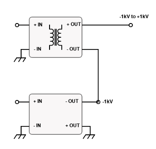
The output voltage of the first module is set to -1kV. The output of the second module can refer to this -1kV.
Isolated 2 kV modules are set in series on the module and are controlled in the 0 to 2 kV range.
The module will produce a voltage that can be controlled linearly from -1 kV to +1 kV, with no significant
nonlinearity or instability during the conversion from negative to positive.
It is important not to leave the output part hanging while powered on, as the output can be electrostatic charged
to a voltage higher than the isolation rating - this can cause damage.
This approach avoids the expense and space of typical off-the-shelf bipolar power supplies, providing a cost-
effective solution for OEM designs.
5. Protect high voltage power supply from voltage transients
In a mass spectrometer, many different potentials may be juxtaposed, so interactions between high-voltage power
sources may occur.
We recommend that systems with multiple high-voltage power supplies include supplementary protection circuits
for each power supply to prevent failure.
If an arc occurs between two high-voltage power supplies with different output voltages but the same polarity, a
power supply with a lower nominal voltage may be damaged by overvoltage.
A high-voltage arc may be a multiple of the nominal voltage of a module with a lower nominal voltage, which can
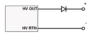
cause a power failure. A good solution is to add a high-voltage protection diode to the output of a high-voltage
power supply with a low nominal voltage.
6. Protect high voltage power supply from reverse current
When there is an arc between high-voltage modules with different polarity, each power supply will attempt to
provide its rated current. This exposes the output to a power source with a higher opposite polarity current.
A power supply with a smaller current may be forced to deliver or absorb more current than it can handle, which
can lead to overload and power supply damage.
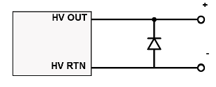
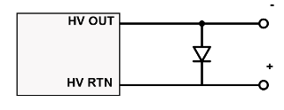
To avoid this problem, we can use a reverse-biased diode return at the high-voltage power supply output. The
diode must be able to carry the current of a high-voltage power supply with opposite polarity.
